
Tri-Five Late Model Power Booster Conversion
By Alan Arnell
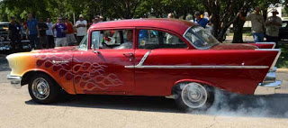
My next upgrade to my Candy Apple Red ’57 Chevy-150 will be a master cylinder upgrade and front wheel disc brakes. Today I will start with presenting my research on the Booster Conversion. I would ask why do they call them brakes, because when you step on the brake pedal nothing breaks. However, with a 58 year old car with original equipment you cannot be 100 percent certain they will not break.
My ’57 is equipped with a single brake master cylinder. Now, I am a purest at heart and wish for my car to be true to its period correctness. With that being said, I have to come to the realization that I live in a large Metroplex. In the Dallas and Fort Worth-North Texas region; traffic may not be as bad as in other parts of the world, but it is bad enough to warrant a modern braking system. Where I live the main problem is that you will be going 70 MPH on a clear roadway to run up on cars suddenly going 25 MPH. After driving new cars with new car brakes; I will have to admit, that I am now spoiled with this new fangled mechanical advantage equipment. Too many times I have been forced to make a scary-panic stops with my 1950’s breaking technology. More than once fear has cut through my chest like an ice pick from the perceived sensation of not being able to stop in time with the fully functioning stock ’57 drum-non power brakes in my ‘57. Function in this case outweighs form.
Do not get me wrong, Tri-Five Chevys had excellent brakes by the standard of their day. In the late 50’s you didn’t need much braking. However, that day has passed into a fond memory. Today’s driving requirements in a urban city would be better suited with a more efficient and arguably a safer brake system.
 Tri-Five’s were designed with a single (piston) master cylinder (MC). A leak in that system’s brake plumbing happening anywhere on the car could render all four wheels completely inoperable. The parking brake in the car back in that day was called the emergency brake for a reason. The manual emergency brake, if you were lucky, was your sole means of backup to any hydraulic brake failure. Brake failure was not all that uncommon back in the day with a single MC. When I was taught how to drive in 1974, dealing with brake failure and what to do to keep yourself alive was an important issue.
With a tandem system, that most of us commonly referred as a dual cylinder, has two pistons instead of one piston operating in tandem, one after another, in a common bore. By placing dual pistons in the MC the catastrophic effects of a failure is minimized. The tandem MC will isolate the effect of a leak to the subsystem, allowing either front or rear to provide partial braking power until you can pull over to the side of the road. So, in short, I am saying a leak in the front will not affect the the rear system. As you can see, the tandem system is safer. Engineers have learned a thing or two through the years to make newer brakes better.


Through the internet and an article in Classic Chevy World Magazine, by Denny Williams, I have researched how to update the single cylinder MC to a Power Booster MC.
You may purchase the whole kit at Danchuk, eBay , etc. I will give the parts suggestions from the articles written in 1984. Things are not the same now as then, but the items listed may give you a place to start while looking for parts for your upgrade.

With a Tri-Five Chevy, I believe, most people would want to have smaller diameter style booster. I think around 9 inches would look the best. I personally prefer that the MC be placed flush against the firewall.
Some MC units have large diameter boosters that are tilted with a bracket holding the MC away from the Fire wall. I have been told; beside the bad ascetics of that type of unit, that type of setup requires quite a bit of modification to install. I have chosen a flush system
 Denny Williams suggests a smaller flush unit from a 1966 Corvette. The setup I will write about is a dual diaphragm vacuum booster. The booster is 9 inches in diameter and is 6 inches in overall length. Size is always important when you put an upgrade on a Tri-Five when the car was not designed for the non stock part or system you might want to install. Still, no matter how much you plan, there will be issues with the building process, size wise. I have found that whenever the measurements are if not checked prior to instillation there will be a problem. But, that is part of the fun, right?
The unit from the ’66 'Vette will fit on any Tri-Five Chevy as long as it is fitted with the standard brake system. Those of you who have an original Treadle-Vac power brake system will need to change the pedal harness setup to make the conversion.
As always, Denny Williams suggest that anyone considering this installation should read through the complete article before determining if this system is what you want.
The reason I wish to install a vacuum booster it to reduce the effort required when applying the brakes. The idiom of, “Stand on the breaks!” started because in days past your leg power was the major power source used to apply brake pressure. My dad really liked our family ‘57’s breaks in the 1960’s, because he had had a ’32 F@$d back in his day, that only had mechanical brakes. The Tri-Five brakes to him had them fancy new hydraulics that worked much better in getting a 2 ton hunk of iron to a complete stop.
The basic idea behind a vacuum booster is to have atmospheric pressure and engine vacuum do the work for you instead of your size number 10 shoes. The dual ’80’s mid size GM “A” cars (Monte Carlo, Cutlass, Regal, etc.) have this type of booster. Brand names of MCs of those cars were generally Moraine or Bendix.
There are four basic connections involved in the installation of a vacuum booster.
- The mechanical connection between the booster and the master cylinder via a rod.
- The vacuum connection between the booster and either the carburetor or the intake manifold, with an 11/32” or 3/8” rubber hose.
- The mechanical connection between the booster and the pedal harness with a rod.
- And, there are 2 hydraulic connections between the dual master cylinder that the proportioning valve, these are stainless steel tubes with double faired ends and fittings.
The pedal has a connecting rod to the booster with an eyelet or pressed on yoke. The rod will be 3/8-24 threads. When you get the power brake booster there are other parts you will need. Such as a check valve, which is installed right on the booster; the push rod, which connects the power brake booster and the master cylinder; a vacuum fitting that is either installed into the carburetor the carburetor or the intake manifold. More than likely you will upgrade your brakes to a disc brake set. If you l do so you will need to have a dual master cylinder form a mid-sized GM car with disc brakes. It is best to get a MC for the same car that you got the booster. Some vacuum booster will have a filter between the check valve and vacuum fitting; these were installed by GM to help eliminate moisture from the system.
WARNING: Brake fluid ruins paint. Cover up your fenders and spread lots of rags below the master cylinder.
Bleeding the brakes. Fill the master cylinder with fresh brake fluid. As the brake bleeding process continues, you will need to keep the bowels of the master cylinder full. DO NOT let them run dry, if you do, you will let air into brake lines and you will need to start the bleeding process all over again. All four wheels will need bleeding. Always start at the wheel furthest from the master cylinder (right rear) and work your way towards the wheel closest to the master cylinder (left front). Caution: spray the wheel cylinder bleeder screws with a rust penetrant the day before to lessen the chance of stripping them. When you have a nice hard brake pedal you can take your next cruise without fear of a catastrophic total brake failure.
Tips: • Use a “ Mighty-Vac” type tool for bleeding the brakes. It allows you to do the job by yourself. Your friends and family will greatly appreciate this tool as they no longer have to sit behind the steering wheel listening to, “Push……..Let Up” a couple thousand times.
This is a good time to pump all the old brake fluid out. Brake fluid is hygroscopic (meaning it collects moisture); this will rust out the insides of the wheel cylinders (common cause of brake failure). Manufactures recommend replacing brake fluid annually, when was the last time you replaced yours? When the fluid runs clear, you have gotten the old junk out.
SAFETY: Test and re-test all parts of a new power booster brake system before you take you valuable Tri-Five out on the road. When you have finished the install/upgrade everyone including yourself will be very impressed with the way it looks on you Classic Chevy. Denny Williams and I consider this new brake system is one of the best modifications that can be done on a “55-“57 Chevy.
Parts suggestions from the Late Great Chevy Club
- Master Cyl. 1968 Chevelle (drum/drum)
- (1) 9/16 to 1/4 Brass Brake Adapter
- (1) 1/2 to 3/16 Brass Brake Adapter
- (2) 3/16 X 3/16 Brass Union @ $.79 ea
- (1) 3/16 Brass Plug
- (2) 3/16 X 40" Steel Brake Line
- (1) 1/4 X 30" Steel Brake Line
Recommended Tools:
 ½” combination wrench
 - 3/8” x 7/16” brake line wrench
- Needle nose pliers
- 2’ -¼” clear tubing to bleed brakes double flare tool
- tubing cutter
- file
- rotary file
- tubing bender

Tech Steps:
 The first step for the MC upgrade is the removal of the brake harness (pedal assembly). The brake harnesses for all three years are basically the same except for the supporting rods that attach to the underside of the dash. The ’55 and ’56 Chevys will have 2 supporting rods which attach to the under-dash. The ‘57’s will have three support rods which connect to the cowl in that are held in place by nuts, which are accessible from the engine side of the cowl. (Assembly Manual Sect 9, Sheet 5.00.-ttp://www.trifive.com/garage/1957%20Chevy%20Index.htm) If you have trouble removing the support rod nearest the fender you may want to remove the light switch and use a ¼-inch drive extension rod and swivel socket to remove the bolt that is securing that rod to the dash. Remember remove all of the support rods from the brake harness.
- Remove the four nuts and lock washers securing the master cylinders to the fire wall. Put the parts and all parts in a plastic freezer or lunch bag and label the items in the bag. You would think you would remember where all the parts go and what they do, but you will be surprised when months later when you are again working on your car you cannot remember. If you can, good for you, you are very special and experienced.
- Remove the lower steering column housing which is secured by the clutch-head screw right under the instrument cluster. This will expose a bracket that secures the pedal harness to the steering column.
- Remove the two nuts securing the bracket which fastens the brake harness to the steering column.
- After unplugging the brake light switch at the brake harness, carefully slip the entire brake harness out of the cowl and from under the dash area.
- Using a chisel, remove the 4 mushroom headed bolts that are spot welded to the brake harness. These are the bolts which originally held the master cylinder in place. Try to be careful not to destroy the threads on these bolts because you will need to reuse two of them. Wrapping the threads with tape should help. The top two holes of the harness must be enlarged. Drill them out to 13/32 inches or 7/6”.
- Remove the original push-rod from the brake pedal by removing the cotter pin and slipping the clevis pin out of the brake pedal. After loosening the locking nut on the assembly, unscrew the rod from the yoke.
- Temporarily install the booster onto the brake harness. Use 2 washers over each of the top two studs to represent the proper spacing that will be required when assembly is installed into the car. The upper 2 studs of the booster should be installed through the upper 2 holes of the brake harness, where the mushroom-headed bolts were removed. The brake harness assembly can be placed in a vice so that you can carefully check the required length for the push-rod when it is installed on the brake pedal.
- The push rod should be as long as possible without beginning to push the diaphragm of the power brake booster. You can push the threaded rod inward and feel when the pressure will exist. Align the threaded rod beside the installed yoke of the pedal and note exactly where the yoke with tape or a marker should be installed onto the threads for the proper length.
- A locking nut should be placed on the threaded rod, and then installed the yoke onto the rod to the premeasured length. Hold the yoke in place then tighten the locking nut up against the yoke.
- If by some chance the threaded push-rod is not long enough and additional length is required, then a coupling nut and stud can be used to join the threaded rod/valve assembly to the original brake pedal yoke. More than likely you will never find a 3/8-24 coupling. What you will end up doing is to get a 5/16-18 coupling nut to drill it out to 21/64” and tap it with a 3/8-24 threads. Along with this coupling nut, you will need a 2” long threaded rod in 3/8-24 which can be used as an extension. Remember a locking nut is required against the yoke and against each side of the coupling nut. What that assembly accomplishes is to increase the length of the rod. The studs of the booster and the holes on the firewall may not line up. Make a paper template or the stud pattern and transpose onto the fire wall. I would check the measurements at least three times. Carefully mark the holes on the cowl, so that the spacing will coincide with the four studs of the power booster.
- Draw parallel lines along the edges for the existing 4 holes to help with measuring. Check the sizes of the holes to be drilled. The lower hole nearest the center of the cowl should be drilled out. Use a pilot drill before drilling the full size hole.


- Using a rat tail file to increase the size of this hole when it comes time for installation. The other I simply will a cut-out of a small amount of metal of the steering column hole in the cowl.
- Make sure that the 4 studs protruding out of the booster are parallel to each other. Many times they will end up point outward. Install a couple of nuts and use vice grips to bend them to the proper place. Many power boosters will have metric threads; ensure to use the correct nuts for the job.
- Slip the brake harness into position and temporarily install the support rods. These will be tightened into place later.
- Two of the mushroom-headed bolts should be installed from the engine side, though the bottom 2 holes of the original four. You may have to tack weld the head slightly to the fire wall to tighten.
- Install washers, lock washers, and the nuts on the two mushroom-headed bolts. Tightening into position.
- Use a washer as a spacer between the booster and the cowl so the booster is not in direct contact with the entire surface of the booster. This will help protect paint on the fire wall. Originally most boosters had a thin rubber gasket over the complete contacting surface.
- Along with the washer/spacer install the power booster through the 4 holes in the cowl, making sure that the booster is in the popper orientation. Slip the push-rod yoke over the pedal as you are placing the booster into position. The check valve, where vacuum line will be connected, should be towards the top of the booster.
- From under the dash install the washers, lock washers and nuts over the four studs from the booster. Tighten into place.
- Install the pin through the yoke and pedal, and then secure it in place with a cotter pin.

- Tighten the support rods, not only the brake harness, but also the dash or cowl depending on the year of the car.
- Install the harness/steering column bracket underneath the instrument cluster.
- Install the lower steering column housing which covers the bracket.
- The vacuum systems on some cars were attached to the intake of the manifold between the carburetor and distributor. This was done with a fitting that screwed into the intake manifold. A stainless steel tube with fitting was screwed into the manifold fitting. A section of 3/8” rubber hose connects the tube to the check valve. Some fittings hand additional outlets for the transmission kick down.
- Most power brake boosters have the vacuum fitting which attaches to the bottom of the carburetor, on the back side. Whatever you use ensure there are no leaks at the fitting or at either end of the hose.
- The hose should be installed on the nylon check valve at the booster. Use hose clamps to stop vacuum leaks.


- Install the pushrod between the booster and MC making sure that it is the proper length. The proper length is a rod which is as long as possible, without activating the master cylinder attached to the booster, and then you should not have to worry about its length. When the master cylinder is secured in place, neither the master cylinder nor the booster should be activated by the push rod between them. If either is activated, the rod is too long
- Slip the dual master cylinder over the two studs of the vacuum booster. Install the proportioning if you install disc brakes. Install the proportioning valve bracket, so do install the washers and nuts at this time.
- Install the proportioning valve bracket before you secure the master cylinder to the booster. Thus the order of items would be: booster, master cylinder, proportioning valve bracket, washer, lock washer and nut.

- Bench bleed the MC and the complete brake system. Again test your work before you take your car for a ride.


This project will help the breaking power of your loved vehicle tremendously.
Links to more Power Brake Posts:
Power Booster Conversion Tri-Five Late Model Part 2
Power to the Front
Move to a Dual Purpose MC and Disk Brakes
Front Disc Brakes for a Tri-Five Classic Chevy
Power Booster Conversion Tri-Five Late Model Part 3
Tri-Five Classic Chevy
Proportioning Valve, Dual Master Cylinder and Brake Lines
Brake Pedal Clevis Relocation After A Power Assisted Disc Brake Upgrade on a Tri Five Chevy.
Brake Troubleshooting for Tri Five Chevy/ Disc Retrofit
Front Wheel Alignment
Citations
- William, Denny. "Late Model Power Brake Booster Conversion." Classic Chevy World Sept. 1984: 5-17. Print.
++++
!!!Support Texas Classic Experience!!!
Did you like the blog? If you did, the best way to support Texas Classic Experience is to share this post! Please tell others that you liked this post by sharing it with your car friends by sending them a link to this page. http://texasclassicchevyexperience.blogspot.com/
No comments:
Post a Comment
Note: Only a member of this blog may post a comment.