Showing posts with label Ball Joints. Show all posts

Sunday, February 21, 2016

FullSizeRender (1).jpg
Front Wheel Bearing-Adjustment, Maintenance and Repair
Lubrication Maintenance of Ball Joints
1955, 1956, 1957 Chevrolet Chevy
  - Alan Arnell


Description:  Best practices for adjustment, maintenance and repair of vintage Chevy Tri Fives’ front wheel bearings and ball joints.


Note:  Correct and timely maintenance of the front suspension Chevy parts must include the lubrication of each to the four ball joints every 1000 miles.  The front wheel bearings must be greased every 10,000 miles to achieve proper wear rates for a 1955, 1956, 1957 Chevrolet Chevy, BelAir, 210 and 150 models.


The wheel bearing must also be properly maintained as a safety precaution.  Bad adjustment to the front wheel bearing will cause lack of steering stability, a tendency to wander or shimmy and causing undo tire wear.  The bearing may destroy itself and the wheel may fall off.  The same is true with the ball joints.


Tools needed:  Tire lug nut wrench, jack, chocks, jack stands, adjustable pliers, diagonal wire cutters, screwdriver, ball peen hammer, grease, grease gun, cleaning rags.

!@#5115180199_large.jpg

Front Wheel Bearings - Maintenance
  1. With weight still on the tires just loosen front wheel lug nuts.
  2. Disconnect the negative side of the battery
  3. Jack up the the car and insert jack stands, check for stability
  4. Remove wheel and tire.  For safe storage, have a container available to put all parts that are removed.   A magnetic metal dish works the best.
  5. Using a screwdriver and a hammer, place the screwdriver tip under the lip flange of the dust cap or sometimes called the grease cap and gently tap and or pry the cap to remove the dust cap. Tap around the cap during removal in a star pattern.  To do this turn the wheel hub by hand rather than stand on your head.
  6. Remove the cotter pin from the end of the spindle by cutting the bent side off with a diagonal wire cutters. With the point of the wire cutter’s blade in the eye loop of the cotter pin,  pry out the cotter pin.  Discard the cotter pin and use a new one.  Never use a nail for a cotter pin.
  7. Using an adjustable pliers or proper size SAE socket and socket wrench unscrew the spindle nut,
  8. Remove the spindle washer.
  9. Pull off the brake drum or brake disc.
  10. Note; To remove the the brake drum it may be necessary to back off the brake adjustment wheel inside the drum.  This may be because of scared drums or badly worn brake shoe linings that hold the drum on preventing easy removal.
    1. On the face of the drum there is an oblong opening that a brake spoon or screw driver must be used to back off the brake adjustment screw.  In later model you have to fight an anti-back-off catch.  The Tri fives do not have those catches.  Be sure to turn the adjustment screw the correct way.  Even though the screw may be completely disengaged the drum may not come off.  Using heat or pry bars, you have to be creative to get this type of offending drum removed!  (I had friends who could not get a rear drum off.  I came to the garage and released the parking brake and the drum fell off!)
    2. If no service has been performed on a brake drum or wheel bearings there may not be an opening to gain access to the adjustment screw.  If there is not a pre made opening you have to find the stamped area made for the opening.  Using a center punch and hammer, pound out the stamped part of the opening.  There a rubber cover plug on the market to use to close up the hole after repair.  I can never keep up with them and leave the hole open if forced to.
  11. Using your fingers remove the outer-bearing from inside the hub.  The inner bearings will remain the hub and may be removed by prying out the inner bearing seal.  Place a rag over the seal and prying device when removing the seal to keep the inner bearing seal from hitting you in the face during removal.  Do not reuse the old seal.
  12. Wash all parts thoroughly in cleaning solvent, then add wheel bearing grease. Or, do not remove the old grease to just add more new grease.  If you do clean the bearings they have to be perfectly clean.

Inspection of bearings:

  1. Note: The Tri Five Classic Chevy had roller bearings are unlike cars of the 70’s and 80’s that had tapered roller bearings.  If you have to replace the front wheel bearings, I would suggest that you upgrade to a roller bearing conversion kit instead of stock replacement  for Tri Fives. The newer bearing are more reliable and require less maintenance.  The kit also allows the retention of factory drum brakes and 14" wheels to keep car original with a bearing upgrade. I bought a kit set from CPP (Classic Performance Products) ,  #5564RBH-K and Speedway Motors #916-31972. Good quality and bolt on installation. Also, I would upgrade due to the exorbitant price of original Tri Five Chevy wheel bearing parts.  Even buying new hubs to go along with the new tapered roller bearing for both sides is less expensive that one wheel set of roller Chevy bearings.  The only reason not to upgrade is if you have to remain stock for whatever reason.5115180331_large.jpg

  1. Check all bearings for cracked bearings separators or worn or pitted balls.  The separators are really plastic holders of the ball bearings.  The separators are prone to cracking and allowing the ball bearings to fall apart. The newer style have metal so called separators.
  2. Check brake drum for “out of round” or scored condition.
  3. Check bearing outer race for looseness in the hub.  Again, the races may be removed with a brass drift punch but it it comes back to it is better to just get new tapered roller bearing hubs.  
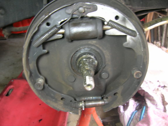
  4. To put grease on and in the bearings, place a glob of grease in you palm and roll the grease into the bearings.  When assembled, do not place additional grease past the outside of the grease washer or in the dust cap.  There is a debate if you need to coat the spindle with grease.  For me I would rather have it and not need it than not have it and need it!
5115180330_large.jpg

Front Wheel Bearing Assembly and Adjustment:

  1. Assemble the bearings and hubs on the spindle to the point you screw on the spindle nut then stop and finish the next steps.
  2. Bolt on the tire/wheel.
  3. While rotating the wheel tighten the spindle nut to 33 ft. lbs.  Check to see if 33 ft. lbs. is enough by placing your hands at the 10 and 2 position on the tire.  Shake the tire back and forth-sideways checking for play.  There should not be any sideward play in the wheel.  If you don’t have a torque wrench and or a socket big enough to torque the spindle nut, just turn the nut while spinning the wheel until you feel the slightest resistance to turning the wheel and back off. From that jerry rigged torque setting loosen and tighten until there is no sideward play in the wheel.
  4. Turn the spindle nut back so the cassel slot in the nut lines up with the cotter pin hole it the spindle. Back off the nut 1/6 of a turn until the next slot lines up with the hole in the spindle.  
  5. Insert a new cotter pin.
  6. Note:  Front wheel bearings should never be set on the loose side as such an adjustment does not bring the balls and races into proper contact.  Final adjustment should have the nut backed off 1/12 to 1/6 of a turn, that is a ½ to 1 flat cassel of the nut.
  7. Spin the wheel to make sure that it rolls freely.  
  8. Properly lock the cotter pin by spreading the end and bending it around the nut.  Install the dust cap. Using a punch or screw driver tap the dust cap on by only hitting the outer lip flange.  Never hit the cap on the top of the dome or it will dent and not fit correctly, as well as look like some FNG did the repair.


++++
#Classicchevy #TriFive #ClassicCar #Chevy #Chevrolet #Belair #Carshow #Custom
#Musclecar   #HotRod #StreetRod #DragRacing #55Chevy #56Chevy #57Chevy


!!!Support Texas Classic Experience!!!
Did you like the blog?  If you did, the best way to support Texas Classic Experience is to share this post!  Please tell others that you liked this post by sharing it with your car friends by sending them a link to this page.  http://texasclassicchevyexperience.blogspot.com/

Don’t forget to visit and like Texas Classic Experience on FaceBook:  LINK to FaceBook
Texas Classic Chevy Experience will post blogs about: Hot Rods, Chevy, Chevrolet, Drag Racing, Car Shows, Classic Cars, Custom Cars, Muscle Cars, How to Tech. posts, Dallas Area Classic Chevy Club, Texas Muscle Car Challenge, Tri-Five Nationals, Lone Star Chevy Convention, Classic Car lists, Classic car links, Spotters guides, Car Shows, Swap meets, Book reviews and More.


 

Tuesday, February 9, 2016

Replacing Ball Joints and Control Arm Bushings


Replacing Ball Joints and Control Arm Bushings

1955, 1956, 1957 Chevrolet Tri Five

  -Alan Arnell


Description:

Disassembly of ball joints, upper and lower control arms (A-arms) and cross shafts in a 55, 56, 57 Chevrolet and the reassembly of the Chevy parts.  


In the Spring of 2006, I was ready for a new project to start on my 1957 Chevrolet Model 150 2-door Sedan. The a-arm/control arm bushings were all worn out, cracked and squeaked.  The ball joints seemed to work okay, but if I were to change the bushings I may as well change the ball joints as


well.  In my repair and replacement I found that the bushings were original.  The ball joints had the holding rivets removed thus implying they had been changed at some point in the car’s life.


A Tri Five Chevy’s front steering system provides stability and handling for the car.  There is a series of rubber bushing used on the Tri Five Chevy that dampens the road vibrations and establish overall control over metal on metal friction the steering joints would have if there were not rubber bushings.  The control arms have bushings at each end.  There are bushings on the axle side and another along the frame of the car.  As you can imagine the bushings will wear out and will cause serious problems over time.


New bushings will restore a car’s factory handling capabilities.  I used Polyurethane bushings.  These bushings are made to allow less deflection than rubber bushings.  If I were to have a completely stock car I would use rubber, however I was looking for a better than stock handling of
my ‘57.  Some will say the polyurethane bushings will make for a harsher ride.  I never noticed any difference after my repair and replacement of the bushings.  My handling improved after the retrofit.  The better handling may have been just better bushing, the Poly or both, I can not say for sure.

LINK TO GET ACCESS TO A FREE FULL LENGTH HOT ROD NOVEL, If you like books about cars check it out.   


Tools that are needed:
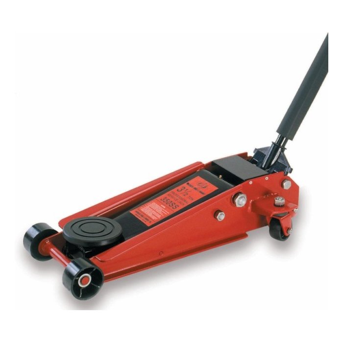
Floor jack, Jack stands, SAE wrench set, SAE Ratchet set, A press or a hammer may be used, Flat head Screwdriver, Optional: Coil spring compressor, ball joint fork, big hammer

++For a list of North Texas Classic Car Shows CHECK OUT TCCE’s Events Page: LINK ++

On March 14, 2006, I pulled on the emergency brake and chocked both sides of one rear wheel. Before jacking up the car, I removed the front shock absorbers that are placed inside of the springs.  I had already replaced the shocks by this time and removal was uneventful.  However putting in the shocks earlier had been very eventful.  Check back later to read about my “Shocking Story LINK” of replacing the shocks.  


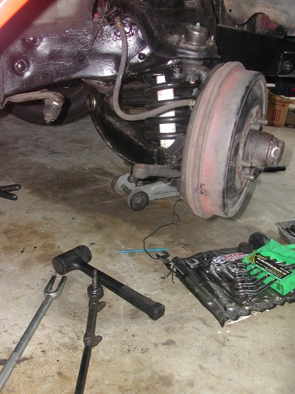
Using my floor jack, I raised the front of the car and used jack stands to hold the car up.  Never just use a jack when working under a car.  With the car on the stands, I grabbed a hold of the headlight eyebrow and gave the car a good shake to see if it was stable.  


From the Chevrolet Master Shop Manual for 1957 Chevrolet:


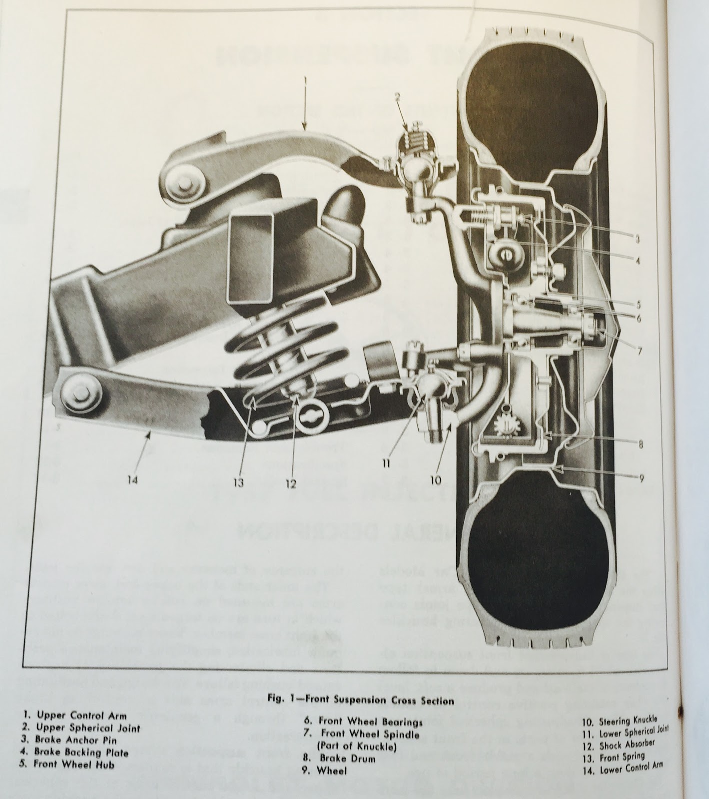
The 1957 Chevrolet Passenger Car Models utilize the S.L.A (short and long arms) type of front suspension with ball type joints connecting the control Arms and steering spindles.


Disassembly:


Removal of the coil springs:
  1. The wheels should be hanging free and not taking any weight of the car.  
  2. Remove the tire and wheel assembly.  If the wheel is not removed its weight will damage the joints during spring removal.
  3. Loosen the four lower control arms cross shaft bushing bolts.
  4. Install a coil spring compressor through the shock absorber mounting hole in the cross member.  The compressor uses holders on both ends and a nut to compress the springs.  You have to be really mindful of the compressed spring.  If something were to happen, just imagine the power that would be released by a compressed spring.  Remember this spring is made to hold up the weight of the car.
  5. Tighten the compressor nut to slightly compress the spring.  I have seen this done with a floor jack, however i will stay true to the Chevy Shop Manual for instructions.
  6. Remove the lower ball joint cotter pin and nut.  I could not get my pin out.  I had to cut the eye off of the pin and take it out backwards.
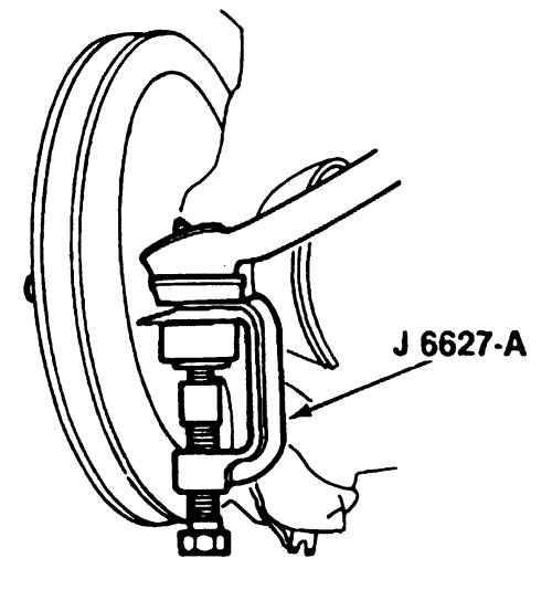
  7. Remove the lower ball joint (where the ball joint attaches to the spindle) with a stud puller #6627. I could not find the 6627 tool. I used a ball joint fork and beat the ball joint in two.  I had a tie rod fork but it was not wide enough. I borrowed a wider fork.
  8. Remove the upper ball joint the same way. Before you take this apart you have to wire or zip tie the spindle or as the manual calls it the drum and spindle assembly, so it will not fall and tear off the rubber brake line.  Remove the brake drum when the wheel is removed will make spindle lighter to hold up from falling.
  9. Remove the four lower control arm inner shaft to crossmember nuts and bolts.  I had a real hard time removing the lower a-arm.  The studs were stripped and turned when I tried to loosen the nuts.  I used a pry bar to hold the cross shaft in place.  
  10. When trying to take the nut off you have to put a  ⅝” inch wrench on the other end to keep it from just turning.  The wrench kept falling off.  I taped it in place. Getting to the driver’s side upper a-arm off required that I had to remove the power steering pump.  The cross shaft was also hard to get out because of the exhaust header.  After a great deal of jiggling the cross shaft was removable without removing the exhaust header.
  11. Unscrew (slowly) the spring compressor and
    remove the spring and then the lower control arm from the car.


Removal of the lower control arm ball joint, cross shaft or bushings:


Note:  The lower control arm ball joint stud is a loose fit in the assembly when not connected to the steering spindle.


Ball joint removal:
  1. Chisel or drill then push out the the rivets that hold the ball joint in place to the control arm if original.  Ball joints that have been replaced will be bolted on the control arm.
  2. Again use the 6627 tool or the ball joint fork and remove the ball joint and seal.
  3. If rivets were removed for the first time drill out the holes to 21/64” so the control arm will accept the new ball joints later.  


Cross shaft and Bushing removal:
There is a special tool #5888 that is used for this removal step.  What the tool does is to keep you from bending and flexing the control while removing the bushings and allows the bushings to be easily pressed out.  Well, I know of absolutely no one who has one.  What you will have to do if

you are unable to secure a 5888 tool is either burn the old bushing out, pull them out, saw them out, bang them out with a hammer and/or chisel all the while not damaging the stamped sheet metal control arms.  I made a centerpiece out of wood and push some of the bushing out with a borrowed press. The piece of wood kept the control arms from collapsing from the force of the press.  I also had to use all the methods listed to get the bushing all out.  You have to be creative.  Also, one bushing I was able to be pull out with just my fingers, the remainder were not that easy.  Fun city!


Repeat for the upper Control arms.


With everything apart now is a good time to clean and paint the parts.  


My springs were good.  They were new and still had the stickers and paint on them.  I reused the springs.


Assembly


Ball joint assembly:
  1. Install the new ball joint with flange against the underside of the control arm.
  2. Attach the ball joint with the supplied new bolts and nuts.  Note:  Only use the supplied nuts and bolts because they are
    made to handle the stress that will be place on them during normal driving.
  3. Tighten the nuts with a torque wrench to 10 to 12 lbs.


Bushing installation:
  1. Coat the outside sleeve of the bushing with a thin coating of grease. Keep the grease off the rubber bushing.
  2. With the cross shaft in the control arm and a three piece spacer in place, place the control arm on a support.  Hand start the bushing into the control arm and over the end of the shaft.  Note:  The end of the shaft with the greatest distance from the end of the shaft to the bolt holes should be toward the front of the control arm.
  3. There are special collars to use with tool # 5888.  I used sockets and a wrench to complete this task and my piece of wood.  Place the collar over the bushing.  Be sure that the three-piece spacers is not overlapping the bushing holes in the control arm.  I placed a piece of wood over the inside of the a-arm to keep the press from smashing the control arm.  
  4. Press the bushing into the control arm until the flange contacts the control arm.  I have known of people installing the bushings with a hammer.
  5. Turn the control arm over and repeat the process with the other bushing.  After the bushings are in place the cross shaft should be able to be rotated by hand.
  6. Install the collar, lock washer and cap screw in each end of the cross shaft.  Do not tighten.


The upper control arm goes together basically the same way.


Install the control arms:
  1. Install the spring compressor and compress the spring. Insure that the compressor can be removed through the top shock mount.  Do this by placing the compressor shaft through the upper shock absorber hole and tighten the nut on the shaft to barely contact the spring with the cross member.
  2. Rotate the spring to make sure it fits in its round holders and seats in the lower control arm and crossmember.
  3. Tighten the spring compressor to draw it to compressed height.  (Again, this can be done with a floor jack.  I use a floor jack because it is a hassle to get the compressor out after use.)
  4. Install the nuts and bolts fastened to the lower control arm to the crossmember and tighten.
  5. Install new rubber seals on the joint stud.
  6. Install the spindle to the control arms.
  7. Releasing the spring slightly to allow the spherical joint studs to enter the spindle bosses.
  8. Install the spherical joint stud nuts and tighten securely and install cotter pins.
  9. Remove the spring compressor.
  10. Place the weight of the car on the front suspension.
  11. Bounce the front of the vehicle to
    centralize the bushings
  12. With weight still on the wheels tighten all lower bushing collar bolts to 45 to 55 foot pounds and upper collar bolts to 35 to 40 foot pounds.  Note: Failure to follow this last step will allow the collar bolts to loosen and fall off!


That is it!


My musing:  I do not want to come of as negative in regards to classic/vintage car projects, however a person could easily become negative.  Nothing ever goes as planned.  But, that is part of the fun.  Thinking of solutions to problems is the real challenge of restoring a car as much as anything.  Invariably, a car part will not fit. The old part will not come off due to rust or ware.  There will be other items on the car in the way that will have to be removed or moved.  Don’t get mad when this happens.  Just accept the fact that this will alway be the case no matter if you Chip Foose or Mortimer Snerd. (A real 50’s reference, look it up.) Be the biggest nut on your car and celebrate when you have beaten the offending part or bolt.  Sometimes when I really have to really fight a part to get it on the car and then become successful, I feel really triumphant.  I have been known to yell out I beat you, you Mo#@$% F@$%&r!  Remember, there is no pressure.  You are doing the project for fun.  Hopefully, you have more time than money!

Get a front end alignment after all suspension repair.

Coming soon: Replacing the tie rods on a Tri Five Chevy.


++++

#Classicchevy #TriFive #ClassicCar #Chevy #Chevrolet #Belair #Carshow #Custom #Musclecar   #HotRod #StreetRod #DragRacing #55Chevy #56Chevy #57Chevy


!!!Support Texas Classic Experience!!!
Did you like the blog?  If you did, the best way to support Texas Classic Experience is to share this post!  Please tell others that you liked this post by sharing it with your car friends by sending them a link to this page.  http://texasclassicchevyexperience.blogspot.com/


Don’t forget to visit and like Texas Classic Experience on FaceBook:  LINK to FaceBook
Texas Classic Chevy Experience will post blogs about: Hot Rods, Chevy, Chevrolet, Drag Racing, Car Shows, Classic Cars, Custom Cars, Muscle Cars, How to Tech. posts, Dallas Area Classic Chevy Club, Texas Muscle Car Challenge, Tri-Five Nationals, Lone Star Chevy Convention, Classic Car lists, Classic car links, Spotters guides, Car Shows, Swap meets, Book reviews and More.